- What does a Spark Gap transmitter and crystal Radio do?
- The radios of Grantville, and what we brought with us, “salvage” radio design
- How does Radio work anyway, and why do we keep talking about the Maunder Minimum
- So what ARE they using if not sparks?
Part 1: How spark transmitters work:
Take the electricity out of your wall, and run wires to a transformer that steps the voltage up from 120 volts (if you live in the US) to 6000 volts.
On the high voltage side of that transformer, place a capacitor across the output of the wires, and then, a spark gap large enough for say, 1000 volts to jump across. The first pulse of current from the transformer charges up the capacitor and stores itself between the plates. As the pulse dies out from the transformer, and before the next pulse can come from the wall, the charge stored in the capacitor surges back into the circuit, jumps across the spark gap, charges the other side of the capacitor, instantaneously surges back through the circuit, jumps the gap again, a second time charges up the capacitor on the first side and continues to surge back and forth in this manner until it completely dies out. Some time later, the next pulse come from the wall, and another spark train (or series of sparks) forms across the gap. This is called a damped oscillation.
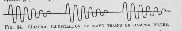
This is distinguished from the output of a CW transmitter, which is NOT modulated. A CW transmitter puts out a signal that looks like this.
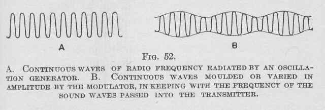 The image on the right is a “dit” from a CW transmitter instead of the train of several hundred damped wave trains like the above (the triangle ones) that would form a “dit” from a spark transmitter. The CW transmitter is NOT modulated. It just “IS”
Figure “B” above is the image of an AM transmitter signal, which gets stronger and weaker as the airwave that hits the microphone gets stronger and weaker. In the spark case and in the case of the AM transmitter, it is the CHANGING of the waves that a Crystal radio can pick up. Without the changing, (called the modulation) the crystal set can pick up nothing. Fancier radios we’ll talk about later are needed to listen to the Morse code from a CW transmitter.
In the spark transmitter the timing of the surges, back and forth spark and spark control the center of the output frequency of the spark gap. As long as the transformer is plugged into the wall, a series of damped waves is formed. Two frequencies are at work here. One is the spark frequency. For spark gaps run off wall current, that’s 120 spark trains, 120 damped oscillations per second. That is, the time from the start of one of the triangles above to the start of the next one. If instead, you are using a portable spark transmitter, run off an automobile spark coil, where the pulses are formed from a buzzer that starts and stops the pulses on the primary side of the spark coil, the spark frequency is controlled by the buzzer. The other frequency – the spark TRAIN frequency, which is the transmitting RADIO frequency is controlled by the capacity and inductance of the circuit, and may be at a speed of several hundred thousand or several million sparks per second.
In Joe Ennis’s second generation spark transmitter he built, the spark frequency is one spark train every millisecond. 1000 spark trains per second, so the AUDIO frequency that you hear on a crystal set, the “on and off ness” of the transmitter is 1000 Hz. The length of each spark train is about 0.1 ms, The SPARK TRAIN Frequency; the Radio frequency you would tune to, is 2.5 MHz, that is 2.5 million sparks per second. So, each spark train in Joe’s transmitter is about 250 sparks long. The first sparks are VERY energetic, at about 2000 volts. But within 0.01 ms (25 sparks) the energy is down to 1000 Volts, and within another millisecond down to 250 volts, dying to less than 100 volts within a half a millisecond.
NOTE: Joe insists that his capacitor is charged in a single pulse and that his tank circuit rings after the sparking ends. I’m not yet convinced.
If we decide to make the width of the gap such that nothing sparks below 100 volts, then Joe gets pulses of 120 sparks with 90% of the energy in the first 25 sparks. Then, there is a gap of 0.99 millisecond where nothing happens then another 0.01 millisecond of LOTS of power dumping into the antenna, followed by 0.99 ms of nothing going on. Historically, spark transmitters used higher voltages – 20,000 volts or so, and had transmitter cut off voltages on the order of 500 volts. It takes about 6000 volts to spark across a 1-inch gap in dry air.
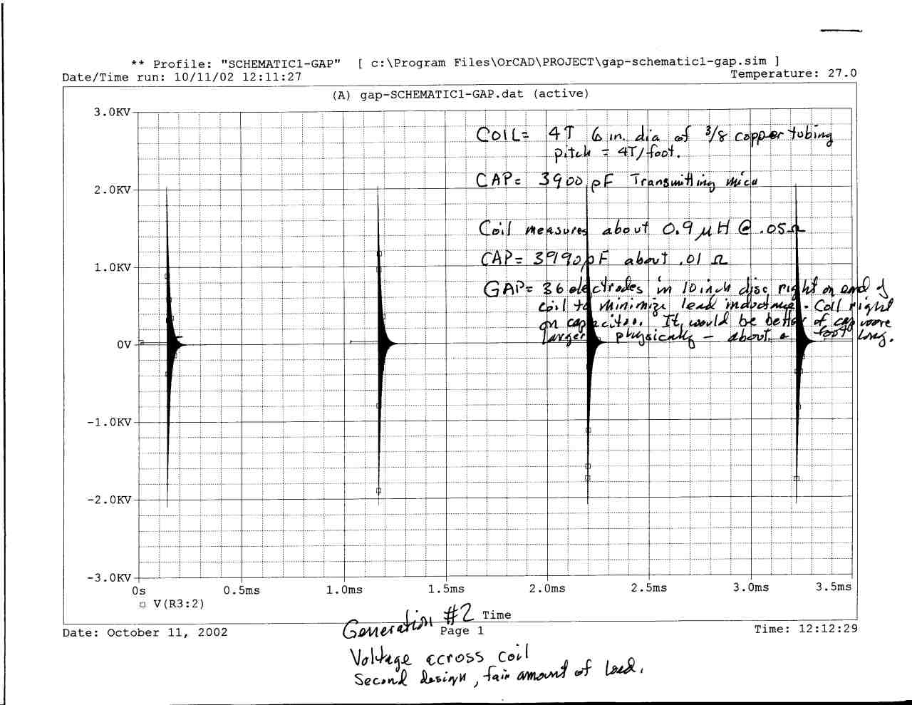 This graph shows the damped waves produced by Joe Ennis’s model 2 1633 transmitter. Each pulse of electricity corresponds to the time the electrode is within the distance needed to make a spark, and the gaps between the pulses correspond to the “dwell time” or the time when there is no sparking going on. You can see how the energy of the pulse is quickly spent into the antenna or the friction of the resistance of the wires.
You tune your radio to the 2.5 MHz spark train radio frequency, and you listen to the 1000 Hz audio buzz. It will sound a LOT like a cheap door bell buzzer.
More capacitance (bigger plates) can stretch out the spark train longer. That’s why Joe asked about mica for building his transmitters. In order to stretch out the spark train historically, HUGE capacitors were built. One of the trans-atlantic spark stations used a bank of 100 champagne bottles filled with salt water, standing in metal sleeves in a salt water bath with the glass of the bottles acting as the capacitor.
Typical commercial spark transmitters used a stack of window glass separated by foil layers. A typical 1 kW transmitting capacitor would be 14 sheets of tin foil 3×5 inches and 8 sheets of glass 5×7 inches.
Now, you can’t DIRECTLY attach the output of the spark to the antenna. If you do, your bandwidth will smear. It’s necessary to COUPLE the antenna to the spark gap with an oscillation transformer. This throws away a lot of the power produced, but restricts the output of the spark transmitter to a narrow band. Joe’s model 2 transmitter has 90% of its power in a band 150 kHz wide. That’s FAR too wide for commercial use, but would be acceptable for experimentation and first transmitters in 1632.
In the real world and in any world where multiple transmitters in the same area were trying to use nearby frequencies the bandwidth of a signal needs to be more restricted. An output transformer would toss about 90% of Joe’s radiated power away, and confine his signal to the central 10,000 Hz. (this is a signal still ten times wider than a CW transmitter would accept, but is quite good for a spark.) I’m frankly surprised by his power / frequency diagrams.
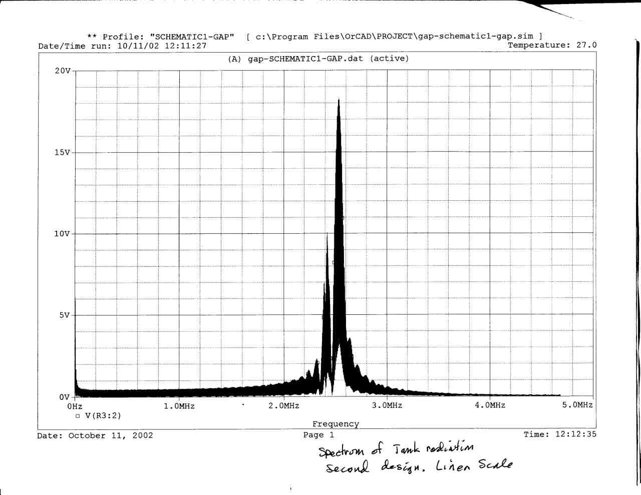 This is Joe’s power/frequency spectrum graph of his model two 1633 spark transmitter. You can see the primary, the secondary peak, and the harmonics moving up and down the band (the little jiggles.)
Oscillation transformers are typically made up of two coils of heavy copper ribbon a ½ inch wide or of two coils of 3/8 inch copper tubing. Two or three turns, 10 to 15 inches in diameter are used for the primary and an identical coil for the secondary.
It is _very very very very important to keep the leads as short as possible in this arrangement. Anything that delays the spark causes an asymmetry in the spark train frequency and causes weird things and loss of power. Joe noted that stray inductance’s as low as 0.01 micro-henry caused problems in his transmitter.
In Joe’s transmitter, he supplied the spark gap with 1800 V DC. In the real world of 1632 or in the real world in the Original Time Line, no such 1800 V DC power supply exists.
Instead, the spark gap was supplied with pulses formed by pulsing DC through a spark coil like that of an automobile spark coil, (Model T spark coils were VERY popular with radio amateurs.) 12V went in, and 10,000 V came out. The buzzer that pulsed the DC into the coil controlled the spark frequency, and the tank circuit controlled the spark train (radio) frequency. The system was keyed by keying the battery supply.
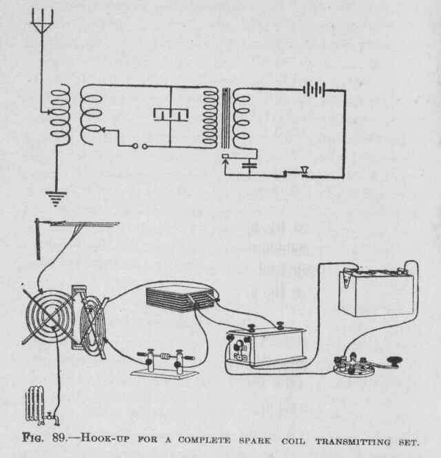 Consider the following spark transmitter:
Working from right to left in the illustration: The battery in the upper right is attached to the telegraph key, and then to the model T spark coil. The buzzer on the end of the coil causes pulses in the primary coil of the transformer, and the making and breaking of the coil cause the transformer to make high voltage on the secondary side. 12V in, 10,000V out. Then the electricity goes back to the battery.
Now, go to the top posts of the transformer. On side of that goes to one side of the capacitor, which is a stack of 10 layers of window glass separated by tin foil. The odd numbered layers are hooked to this wire; the even numbered layers are hooked to the other wire. Then we go back to the transformer.
Now, come off the first lead of the capacitor again, and a wire goes to one side of the spark gap, then there is a small air gap, and then off the other side of the gap to one end of the primary coil of the output transformer. Then, back from the other end of the output transformer primary and back to the capacitor.
Finally, the start and end of the secondary side of the output transformer are hooked to ground and to the antenna. Note that the connections to the output transformer are moveable so that they can be “tuned” for the wavelength you’re trying to send.
Joe suggests instead of keying the power supply, keying a capacitor on the tank circuit to ground shifting the output frequency. It’s certainly doable. It would have the effect of making key-up and key-down on the radio SOUND DIFFERENT but the output would be continuous. So instead of dit dit daaaaah you would hear DEEEaaaaDEEEEaaaaaDEEEEEEEEEaaaaa which would be weird, but you could learn to read it. After all, railroad guys learned to read clickCLACKclickCLACKclick………CLACK which I still think is weird.
Quite honestly, the more I look the transmitted spectrum of the spark transmitter above, the less I like it. The power waste is INCREDIBLE. The portable radios that Gayle and Rebecca took with them have operational power inputs of approximately 60 watts. With any luck, they manage to couple approximately half of that into the antenna in a bandwidth of 1000 Hz, so that they get a power density of 30 watts per kHz. and an absolute power output of 30 watts.
A spark gap transmitter running off the same 60 watt power supply will couple at most 3 watts into the antenna, and that will be spread over 150KHz bandwidth for an effective radiated power density of 0.02 watts per kHz.
Amateurs in the US, using 600 watt spark transmitters powered by 120 volt wall circuits, ( 5 amps of current pulled from the wall ) generally figured that they would be able to send signals 50 to 75 miles. The American Radio Relay League was established to deal with the short distances available to Hams.
Of course, they were using 200-Meter bands, once they moved up, things got better, but remember, WE are doomed to using 80, 160 and 200 meters ourselves….. due to the Goll Darned Maunder Minimum.
Much of this information comes from Kendall and Koehler, Radio Simplified: What it is, how to build and operate the apparatus, John Winston publishing, first edition 1922 (copyright expired) and from the recent experimentation of Joe Ennis.
Summary: The things I don’t like about spark transmitters
- They waste power
- They are massively dangerous.
- They can be heard with crystal radios and do not need fancy up-time radios to listen to, so they have no signal security.
- They are downtime copyable and operable if captured.
Part 2: Crystal Radios.
To begin with, a crystal radio works just like any other radio, but without the amplifiers for radio/audio frequency signals, or local oscillators as used in the common superheterodyne radio.
Let’s begin with the transmitted signal, which is a carrier wave at the transmitting radio frequency of the station, say, 1000 kiloHertz (thousands of cycles per second). For an AM (amplitude modulation) broadcast station, the carrier signal is modulated by an audio frequency signal ranging up to several thousand Hertz, which causes the signal to vary in amplitude at the frequency of the audio signal.
When the modulated wave reaches the antenna of the receiver, some of its energy is captured by the antenna. Ideally, the antenna is resonant at the radio frequency of interest, that is, at least a quarter wavelength long. Generally, the longer and more tuned to resonance the receiving antenna is, the more signal from the station is available to be heard.
The received signal is carried to a tank circuit, typically an inductor (coil of wire), and a capacitor (which we discussed above already). The inductor and capacitor are connected in parallel or in series with each other, usually in parallel. The tank circuit acts as a band pass filter, and when it is resonant at the frequency of the received signal, it will “ring”, just as a tuning fork does, storing the energy of the signal.
Signals of different frequencies will not be stored in the tank circuit, but will pass on to “ground”. Some simple sets, such as the Oatbox, use only a coil of wire with taps on it for the tank circuit, and rely on the self capacitance between the turns of wire in conjunction with the inductance of the coil to achieve a resonant condition. Tuning this circuit is done by selecting different taps for the antenna, bringing different amounts of inductance (and capacitance) into play.
Next, a portion of the energy in the tank circuit is taken by the detector, which is a rectifier, allowing the signal through on only half of its alternating cycle, rejecting the other half; this changes the ac signal to a pulsating direct current. Were it not for the detector, the positive and negative halves of the alternating current signal on reaching the headphones would essentially cancel each other out .
The headphone circuit is next. A diaphragm in the earphone, which moves the air to transfer the sound to your ear, can mechanically follow the audio frequency changes in the amplitude of the signal but not the rf signal, which moves too fast, and passes the rf signal on to ground. Some references would have you believe that the radio frequency and audio frequency signals are split apart by the detector – not true; that really takes place in the headphones.
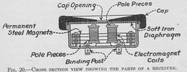 This is a cross-section of a simple high impedance headphone.
Making a crystal radio is very very simple. Consider the classic “oatbox” radio.
You start by winding 52 feet of hookup wire around the outside of an oatmeal box.
Wind forty turns onto the box. I wind the turns onto the box by holding it between my knees and then winding the wire off the spool around the box. Make sure the turns stay snug, side by side. Every five turns, twist an eyelet in the wire — strip off the plastic coating on the eyelets, but don’t cut the wire — as shown below Then continue winding. It may help to add masking tape as you go to hold the wire in place.
Quaker Oats box crystal set.
Any competent jeweler in 1633 can make a headset, the wire for the coil is nothing special, the form for the coil does NOT need to be an actual oatmeal box, and you can just make the coil longer or shorter to adjust it to work.
Fancy variations are possible, but the reality is that a crystal radio is dirt simple. Don’t be taken aback by the mention of a detector above either. A perfectly good detector can be made from a hunk of lead ore (nothing special, just a hunk of rock… really.) and a sharp wire to poke into the rock until you get a signal.
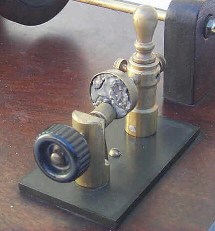
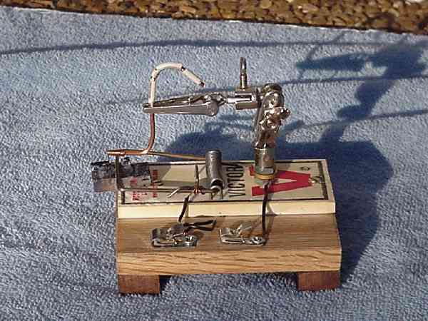
Here are two detectors, one from the early 1900’s the second a home built detector. Both are built to use a lump of lead ore (galena)
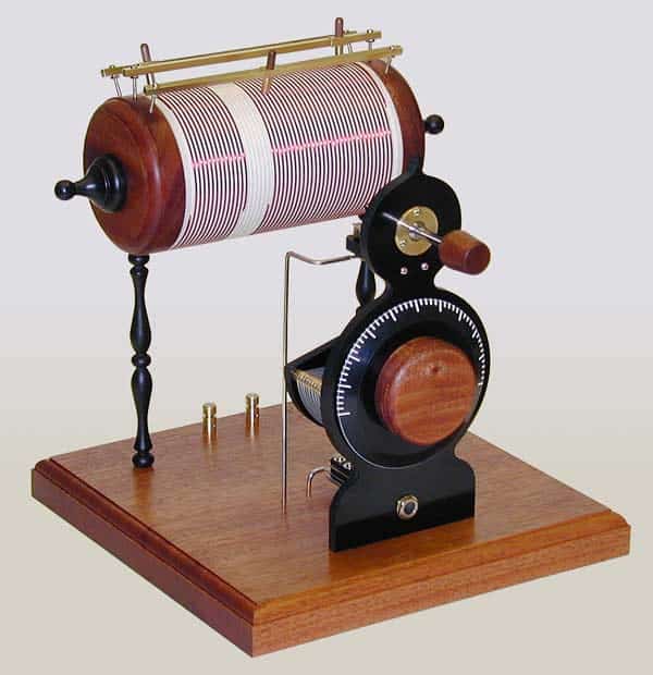
Of course, you can spend inordinate amounts of time to make ELEGANT crystal radios if you want to. This, for example was the clear winner in the 2001 crystal radio building contest – freestyle – master division. The builder built everything including the air-variable capacitor, the detector, the coils, everything in his home shop. Amazing.
So, crystal radios are simple to build, work fine, are well within the ability of 17th century technology and will be GREAT for listening to the VOA. The 2002 crystal radio builders challenge contest winner logged 1294 stations with a record distance of over 3000 miles in the course of a month using no batteries, no power of any kind, just a crystal radio, home made headphones, and persistence and care. Which, frankly, is my concern. Other than VOA which we WANT everyone to listen to, I’m not interested in folks listening in to our military and diplomatic communications.
So, I relegate crystal radios and spark transmitters to the French. (And possibly the Chinese.)